Flexible sensors often look simple from the outside. A thin strip bends, a conductive layer changes resistance, and the signal is read by a circuit. In practice, especially in wearable bioelectronics and autonomous systems, that signal depends on a chain of mechanical and electrical behaviour that has to be understood carefully.
A recent study by researchers in the Netherlands and India gives a useful example of flexible flow sensor testing. The researchers developed an inkjet-printed titanium carbide nanoparticle-based flexible flow sensor, then tested it across several settings: controlled bending, underwater flow, wind flow, and finally airflow-source navigation using a mobile robot.
The authors used a CellScale UniVert mechanical tester to apply controlled bending to the flexible cantilever sensor while measuring resistance change. That step helped connect cantilever displacement to electrical output before the sensor was placed in more complex air and water flow conditions.
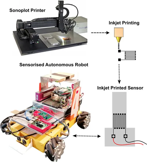
Inkjet-printed flexible flow sensor workflow. The graphical abstract shows the broad workflow of the study: a SonoPlot printer was used for inkjet printing, the TiC strain gauge was patterned onto a flexible sensor, and the printed sensor was later integrated onto a sensorised autonomous robot. Adapted from Sengupta D. et al. 2026. ACS Applied Electronic Materials.
Why Flexible Flow Sensor Testing Matters for Bioinspired Autonomous Systems
Many flow sensors used in autonomous systems are inspired by biology. Fish, insects, and marine mammals have all shaped how researchers think about flow sensing. A fish lateral line, for example, is not measuring flow in the way a benchtop instrument would. It is responding to motion in the surrounding water through small biological sensing structures. That idea is appealing for robotics, but copying it in a flexible device takes some work. The sensor has to bend, recover, and still produce an electrical signal that can be interpreted after the device is mounted on a moving system.
That is where flexible flow sensor testing becomes useful. A flexible cantilever flow sensor does not only detect flow. It bends under flow, and the amount of bending affects the strain in the sensing element. If the sensing element is piezoresistive, that strain then changes electrical resistance. The mechanical and electrical parts of the sensor are tied together.
This is similar to challenges seen in other wearable bioelectronics research. In our previous research highlight on flexible pressure sensors, mechanical deformation and electrical output were also closely linked. The materials may differ, but the underlying question is familiar: how does a flexible device turn deformation into a measurable signal?
In the present study, the authors were interested in flow-aware autonomous systems. Their final demonstration used a robot navigating toward an airflow source, but the device-level problem sits comfortably within wearable bioelectronics, flexible electronics, and soft sensing research.
Inkjet-Printed Titanium Carbide for Flexible Electronics
The sensor was built around a heat-stabilized polyester cantilever with a serpentine titanium carbide, or TiC, nanoparticle strain gauge printed near the hinge. That placement matters because the base of the cantilever experiences relatively high strain when the free end bends under flow.
The researchers formulated a TiC nanoparticle ink using a solvent mixture, binders, and surfactant, then optimized properties such as viscosity, surface tension, conductivity, and wettability for inkjet printing. TiC was chosen because of its electrical conductivity, chemical robustness, and stable dispersion behaviour in the ink formulation. The authors reported that the prepared ink remained visually stable over at least two months under ambient storage, with no obvious sedimentation, aggregation, or degradation.
The printed sensor design is also important from a flexible electronics perspective. Rather than attaching a separate rigid sensing element, the authors patterned the active material directly onto the flexible substrate. The result was a thin cantilever with an integrated piezoresistive strain gauge.
At the microscale, SEM and EDX imaging showed a network of TiC nanoparticles in the printed meander. The proposed sensing mechanism combined two effects. First, the serpentine geometry behaves somewhat like a conventional strain gauge, where deformation changes resistance. Second, the TiC nanoparticle network changes as conductive domains move closer together or farther apart. Under tensile strain, the overlap between neighbouring conductive domains decreases, increasing resistance. Under compression, the overlap increases, reducing resistance.
That bidirectional response becomes useful later when the sensor is tested in forward and reverse airflow.
Flexible Flow Sensor Testing with Controlled Bending
Before looking at flow, the researchers first examined how the sensor responded to bending. This step is easy to overlook, but it is one of the more useful parts of the study for researchers working in wearable bioelectronics.
The authors used two bending approaches. For dynamic displacement testing, a minishaker applied oscillatory motion to the cantilever tip. For quasi-static testing, they used the UniVert fitted with a 100 N load cell. The sensor was clamped, positioned against the moving piston head, and displaced downward in a controlled way while resistance change was recorded.
By applying known tip displacements, the authors could observe how the printed TiC strain gauge responded before introducing the more complicated loading conditions created by air or water flow.
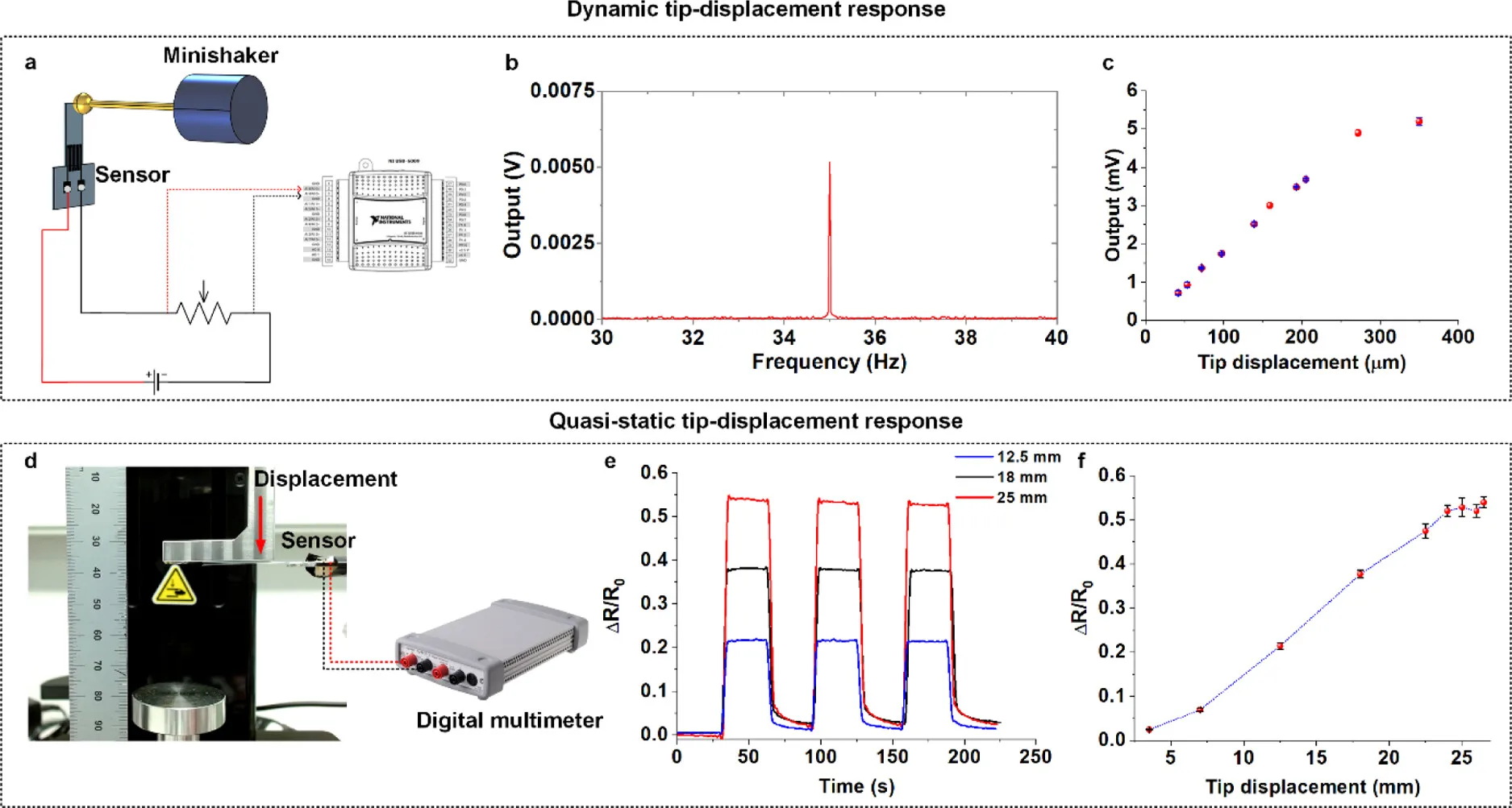
Controlled bending characterization of the printed flow sensor. Panel (a) shows the dynamic tip-displacement setup, while panels (b) and (c) show the sensor response to oscillatory input. Panel (d) shows the quasi-static bending setup using the CellScale UniVert mechanical testing stage. Panels (e) and (f) show how normalized resistance changed during repeated tip displacement tests and how the response varied with displacement. Adapted from Sengupta D. et al. 2026. ACS Applied Electronic Materials.
The quasi-static tests used tip displacements from roughly 3.5 mm to 26.5 mm. The sensor response was approximately linear up to about 18 mm of downward displacement, then began to saturate after about 22.5 mm. The authors attributed this saturation to large-deflection behaviour. As the cantilever bent farther, it progressively aligned with the direction of piston movement, limiting additional strain in the sensing region.
That observation becomes useful later, because a similar saturation trend appeared during flow testing. The bending test did not exist as a separate mechanical measurement. It helped explain why the sensor behaved the way it did under fluid loading.
Flexible Flow Sensor Testing in Water and Air
After characterizing the electromechanical bending response, the researchers evaluated the sensor in water and air.
For underwater testing, the sensor was placed in the central uniform flow region of a water circulation tank. The cantilever was oriented so that water flow bent it and generated tensile strain in the printed TiC strain gauge. The researchers tested water flow velocities from about 0.05 to 0.7 m/s. At lower velocities, the resistance response followed a quadratic trend. At higher velocities, above about 0.4 m/s, the response moved into a saturation regime.
A similar pattern appeared during wind tunnel testing. The sensor was exposed to airflow velocities from about 2 to 30 m/s. At lower airflow velocities, below roughly 10 m/s, the response again followed a parabolic trend. At higher velocities, above about 14 m/s, the response began to saturate.
The authors used finite element fluid-structure interaction modelling to interpret these observations. The model suggested that, at higher flow velocities, the cantilever bends far enough that its plane becomes more aligned with the flow direction. Once that happens, additional flow does not produce the same increase in strain near the hinge.
This is where the earlier UniVert bending work becomes relevant. The controlled bending experiment showed saturation during large deflection, and the flow experiments showed a related saturation behaviour under fluid loading. For researchers developing piezoresistive sensor testing protocols, this is a useful reminder: the electrical response is not just a material property. It is shaped by geometry, boundary conditions, deformation mode, and the way the sensor is loaded.
From Bioinspired Flow Sensors to Autonomous Robotics
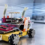
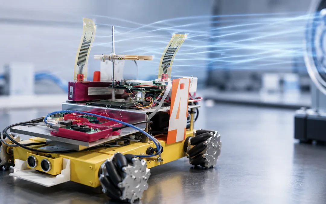
The final part of the study moved beyond benchtop calibration. The researchers mounted two identical flow sensors orthogonally on a Nexus mobile robotic platform. A custom acquisition system used two voltage divider circuits, an Arduino Uno, and the robot’s onboard Raspberry Pi. With the two sensors aligned to local coordinate axes, the robot could use local airflow measurements to move toward a fan.
This is the part of the paper that makes the autonomous robotics angle work well for the blog. The sensor was not only characterized as a flexible electronics device. It was incorporated into a mobile system and used for source-seeking navigation.
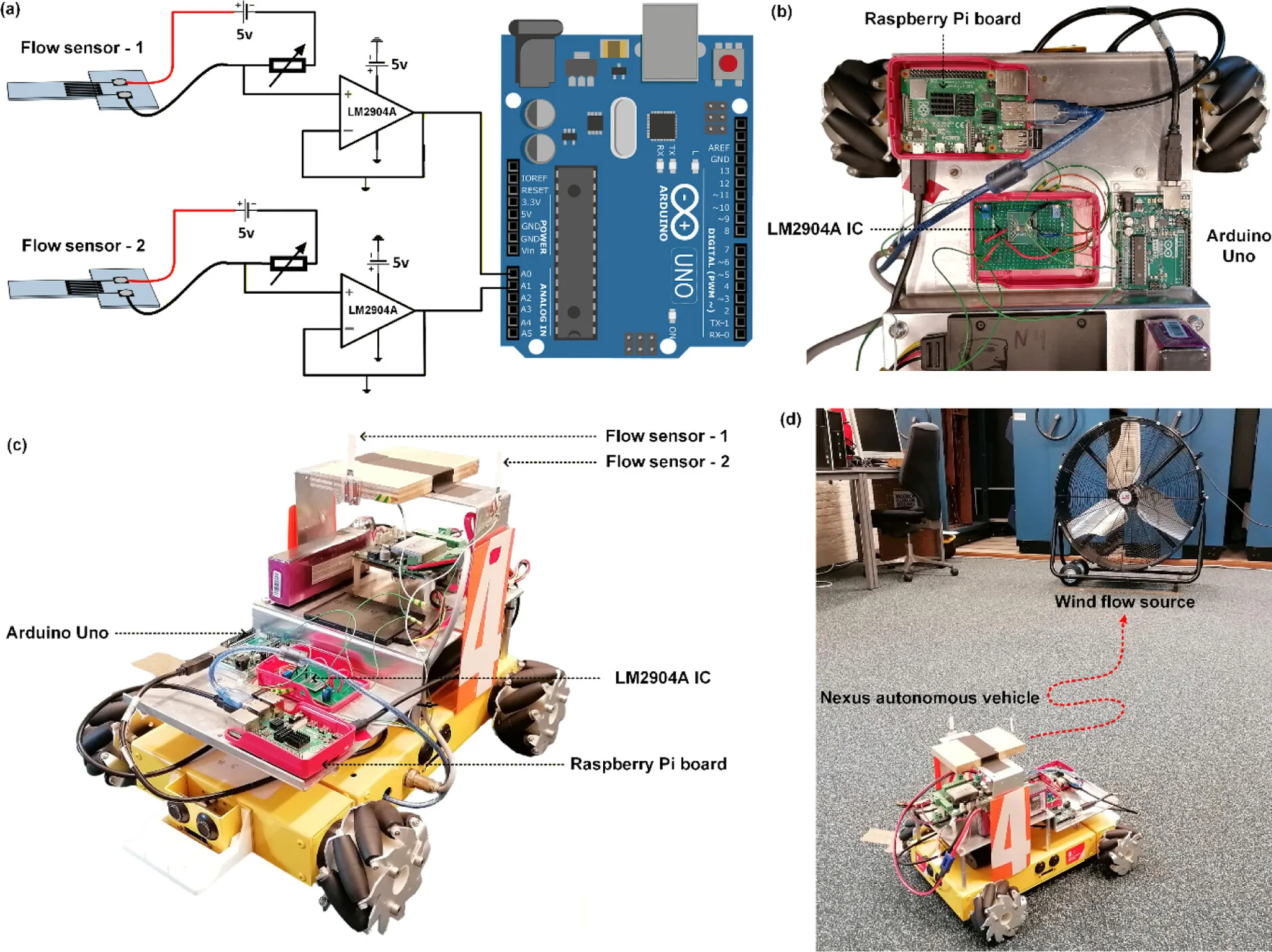
Printed flow sensor integration on an autonomous robot. Panel (a) shows the two-channel acquisition circuit used to read the two flow sensors. Panel (b) shows the onboard data acquisition setup and Raspberry Pi controller. Panel (c) shows the Nexus mobile robot with two sensors mounted at the top for wind-direction sensing. Panel (d) shows the indoor airflow-source navigation setup with the fan and robot. Adapted from Sengupta D. et al. 2026. ACS Applied Electronic Materials.
This robot demonstration connects to our previous research highlight on mechanical testing of smart textiles and robotic fabrics, where flexible materials were also treated as active functional components rather than passive structures. In both cases, material mechanics sit close to system behaviour.
Using the UniVert for Flexural and Bending Testing in the Study
The UniVert was used in a specific and practical way in this paper. The authors needed to know how a flexible cantilever sensor responded when its tip was displaced by a controlled amount. The UniVert provided that controlled displacement while the electrical response of the printed TiC strain gauge was recorded.
For flexible flow sensor testing, that kind of step is valuable because flow itself can be difficult to isolate. A sensor placed in a wind tunnel or water circulation tank experiences fluid loading, changing drag forces, bending, electrical response, and sometimes packaging effects at the same time. By first bending the cantilever mechanically, the authors could study the relationship between displacement and resistance change more directly.
The result was not a single stiffness value or a pass-fail test. Instead, the bending experiment helped map an operating regime. At moderate displacement, the sensor response increased in a roughly linear way. At larger displacement, it began to plateau. That mechanical behaviour helped make sense of the flow calibration results, where the response also saturated at higher velocities.
This is a good example of how flexural and bending testing can support wearable bioelectronics research. The instrument is not only used to test strength. It can also be used to connect mechanical deformation with electrical signal generation in flexible sensors.
The UniVert for Wearable Bioelectronics and Flexible Sensor Research
The UniVert is a mechanical testing system used for controlled loading of soft materials, biomaterials, tissues, and flexible devices. In wearable bioelectronics and flexible electronics research, that control can be useful when researchers need to apply known mechanical inputs and observe how a device responds.
In this study, the UniVert was used for quasi-static flexural and bending testing of an inkjet-printed flow sensor. In other wearable bioelectronics applications, similar test approaches may be used to study flexible pressure sensors, stretchable conductive materials, smart textiles, soft robotic components, adhesive interfaces, or sensorized substrates.
The main point is not that every flexible sensor should be tested in the same way. It is that mechanical behaviour often becomes part of the signal pathway. A flexible sensor bends, compresses, stretches, buckles, or recovers, and the electrical output follows from that deformation. Controlled mechanical testing gives researchers a way to slow that process down and examine it under known conditions.
For this paper, flexible flow sensor testing helped bridge the gap between a printed TiC strain gauge and a robot that could navigate using local airflow. The UniVert appears in the middle of that story, where a known displacement was applied and the resistance response was measured. It is a relatively small part of the full experimental workflow, but it is an important one. Without that controlled bending step, the later flow response would be harder to interpret.